
How to Integrate a Laser Rangefinder Module into an EO System
Adding a laser rangefinder to an electro-optical system looks simple on a block diagram. Find some space, connect the power, add a communication line, and start reading distance.
Real hardware is rarely that easy.
Inside an EO head, the rangefinder has to share a small enclosure with visible cameras, thermal cameras, controller boards, gimbal motors, cables, optical windows, and power electronics. A small choice made during packaging can later appear as weak ranging, alignment drift, blocked optics, or unstable communication.
Good laser rangefinder module integration starts before the enclosure is finished. The rangefinder needs to be treated as part of the EO system from the beginning rather than added after everything else has already found a place.
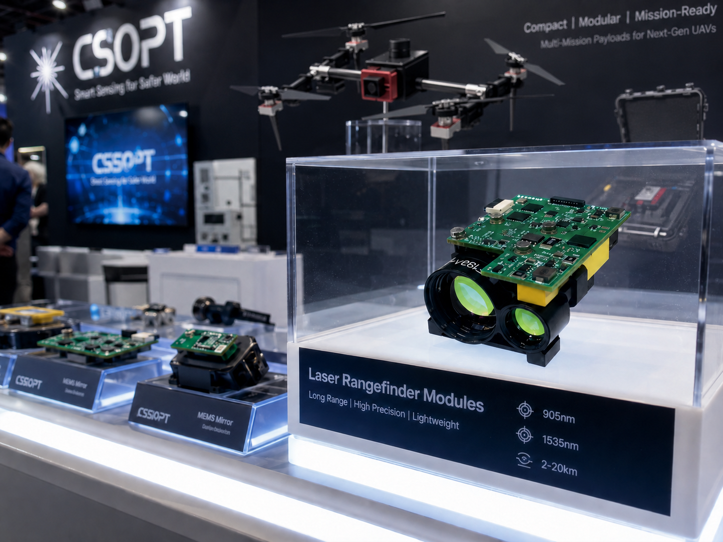
CSOPT Limited supplies 1535 nm laser rangefinder modules for EO/IR and other optoelectronic equipment, with ranging options from 3 km to 20 km. Different configurations are available for supply voltage, beam divergence, ranging frequency, electrical interface, and mechanical requirements. OEM configurations can also be adapted to fit different host systems.
Laser Rangefinder Module Integration Starts with the EO Layout
Start with the complete sensor head, not the rangefinder by itself.
Mark the locations of the visible camera, thermal camera, controller, power board, gimbal axes, optical window, connectors, and cable routes. Then look for a position where the ranging channel has a clear optical path without making life difficult for everything around it.
The rangefinder needs more than physical space. It needs an unobstructed transmit path, a clear receive path, stable mounting, clean electrical power, a communication channel, and a known relationship with the camera line of sight.
Define What the EO System Actually Needs to Measure
A requirement such as “we need 10 km ranging” leaves a lot unanswered.
What will the target look like at 10 km? Is it a building, a vehicle, a wall, a tower, or a much smaller object? Is 10 km the normal working distance, or is it only the farthest distance the system may occasionally need?
The answer matters because laser ranging is affected by target size, surface reflectivity, atmospheric visibility, beam divergence, pointing accuracy, and the way the module is installed.
Before choosing a laser rangefinder module for EO system use, it helps to write down the real operating conditions.
This information is usually much more useful than choosing a module from maximum range alone.
Choose the Position of the Ranging Channel
The first empty space inside the EO head is not necessarily the best place for the rangefinder.
Place it too close to a housing wall and part of the outgoing beam may be clipped. Put it behind a narrow opening and the optical path may lose margin after the front window and mounting parts are installed. Face the connector in the wrong direction and the cable may end up crossing the camera or rangefinder aperture.
Gimbal movement also needs attention.
A cable that looks relaxed when the payload is pointing forward may become tight near the end of its pan or tilt travel. Check the rangefinder position with the EO head moving through its full mechanical range.
Shared Window or Separate Aperture?
Many EO systems place the camera and rangefinder behind one front window. Others give the laser channel its own opening.
A shared window can make the enclosure cleaner and easier to seal. The window still has to transmit both the camera wavelengths and 1535 nm laser light with acceptable loss.
Window material, coating, thickness, angle, and clear aperture all matter.
A separate aperture gives the ranging channel more freedom, but it also adds another sealing point and another mechanical feature to the housing.
Neither option is automatically better. The right choice depends on the optical bands, enclosure size, and internal layout.
Choose the Right Laser Rangefinder Module for EO System Use
Maximum ranging distance is important, but it should not be the only number used when selecting a module.
CSOPT offers 1535 nm ranging options from 3 km to 20 km. Across that range, input voltage, beam divergence, ranging frequency, size, and weight can vary.
A compact short-range unit may fit easily inside a small gimbal. A longer-range unit can ask much more from the mechanical space, power supply, and payload weight budget.
The right laser ranging module is the one that fits the real working conditions of the EO system.
Range, Beam Divergence, and Target Size Belong Together
Beam divergence tells you how quickly the laser footprint expands as distance increases.
A 0.3 mrad beam grows by roughly 0.3 m for every kilometer of travel. At 5 km, the footprint is roughly 1.5 m across. At 10 km, it is around 3 m.
A 0.5 mrad beam spreads more.
Why does this matter?
A zoom camera may show a distant vehicle as a clear object in the center of the screen, while the laser footprint covers the vehicle and part of the area around it. A small pointing error becomes much more noticeable as distance increases.
Beam divergence should be considered together with target size, working distance, camera field of view, and pointing stability.
Mechanical Layout for Laser Rangefinder Module Integration
A rangefinder needs a stable mounting surface.
Thin brackets, uneven seating surfaces, or a housing under mechanical stress can allow the optical axis to move slightly as the payload heats up or the gimbal changes direction.
A tiny movement may mean very little at 200 m. At several kilometers, the same angular movement can matter a great deal.
Keep the Transmit and Receive Paths Clear
Do not check only the nominal center line of the laser.
Leave enough clearance for manufacturing tolerance, bracket position, optical-window position, and assembly variation.
Window frames, adhesive edges, lens barrels, cable bundles, screw heads, and internal structural parts can all enter the optical path if the clearance is too tight.
Saving a few millimeters inside the enclosure is rarely worth it if the transmit or receive aperture ends up partially blocked.
Use a Rigid Mount but Keep the Module Accessible
The rangefinder should sit against stable reference surfaces and should not depend on a flexible bracket to maintain its angle.
Service access matters too.
Leave enough room to reach the connector, remove the module, and make alignment adjustments if needed. If the rangefinder cannot be removed without taking out a camera and several circuit boards first, later service becomes unnecessarily difficult.
Do Not Ignore Cable Strain
Cables look harmless, yet a short, stiff cable can pull surprisingly hard inside a compact EO head.
Secure the cable before it reaches the module and leave enough bend radius near the connector.
Move the gimbal through its full travel and watch the cable. The mount should hold the optical axis without having to fight against cable tension.
Plan Power and Communication Early
Electrical decisions are easier to change while the internal layout is still flexible.
Different rangefinder configurations can use different supply voltages. Check the selected unit against the EO power board rather than assuming every rangefinder uses the same supply.
Look at voltage, available current, connector rating, grounding, DC-DC conversion, and slip-ring capacity when the payload uses a rotating electrical connection.
TTL or RS-422 for the EO Controller?
TTL and RS-422 are both common choices for rangefinder communication, but the installation environment makes a difference.
For a short link between nearby circuit boards, TTL may be enough.
If the cable passes close to gimbal motors, switching converters, or a slip ring, RS-422 is often easier to keep stable.
Give the Rangefinder Clean Power
A pulsed laser does not draw power in exactly the same way as a camera running at a relatively steady load.
Leave reasonable electrical margin and pay attention to grounding. Motor drivers and switching power supplies can make a compact EO enclosure electrically noisy.
If serial communication becomes unstable only while the gimbal is moving, the communication protocol may not be the cause. Cable routing, grounding, or motor noise can be worth checking first.
Optical Alignment Is Where EO Integration Becomes Real
A rangefinder can return an accurate distance and still measure the wrong object.
Its optical axis needs a known relationship with the visible or thermal camera. The camera and rangefinder do not have to occupy exactly the same physical axis, but the angular offset between them must remain controlled.
Why Boresight Error Matters More at Long Range
Angular error becomes a larger physical offset as distance increases.
An offset of 0.5 mrad corresponds to roughly 0.5 m at 1 km.
At 10 km, the same angular offset becomes roughly 5 m.
This is why alignment that looks perfectly acceptable across a workshop can be misleading for a long-range EO system.
Whenever practical, check boresight at distances that reflect the real working range.
Check Alignment at Real Camera Zoom Levels
A zoom camera changes how much of the scene is visible on the display.
At narrow field of view, even a small angular difference between the camera and rangefinder can move the ranging point noticeably away from the screen center.
Check the relationship at the zoom settings operators are likely to use.
If the EO software applies a crosshair offset, keep the mechanical alignment information separate from the digital correction. That makes recalibration much easier later.
The Front Window Is Part of the Laser Path
The front window is not simply a protective piece of glass.
Its material and coating affect how much 1535 nm laser energy leaves the EO head and how much returned light reaches the receiver.
A window selected mainly for visible or thermal imaging should not automatically be assumed to work well with the rangefinder.
Check Window Transmission at 1535 nm
Ask for the optical transmission curve around the wavelength used by the module.
Check the coating, window thickness, incidence angle, usable aperture, and edge areas where adhesive or mechanical frames may enter the optical path.
If the module sits at an angle behind the window, trace the real transmit and receive paths rather than checking only the front view.
Watch Internal Reflections and Contamination
Window surfaces, metal frames, nearby lenses, and bright internal surfaces can reflect unwanted energy back toward the receiver.
Dust, fingerprints, moisture, and condensation can also weaken the optical path.
Some of these effects may be barely noticeable at short range and become much more important near the far end of the required distance.
LRF Integration into EO Payload Electronics Should Stay Simple
The host controller usually needs to do only a few things with the rangefinder: send a ranging command, read the reply, decide whether the returned value is usable, and pass the distance to the rest of the EO system.
Keep this chain easy to follow.
Laser Rangefinder Module Integration at the Communication Layer
Keep rangefinder communication in one clear part of the firmware or host software.
Record the baud rate, parity, stop bits, command format, reply format, distance units, timeout behavior, and power-up state.
If the rangefinder has single-shot and repeated ranging modes, give each command a clear place in the control logic instead of scattering serial instructions across different screens or functions.
Do Not Let an Old Distance Look Like a New One
If no fresh measurement arrives, the EO display should not continue showing the last distance as though it were current.
Where the communication format allows it, use a clear state such as valid, unavailable, or timed out.
This makes the operator interface easier to understand and makes commissioning faults easier to trace.
Heat and Electrical Noise Still Matter
An EO head may contain several heat sources in a small volume: camera electronics, processors, motor drivers, power converters, and the rangefinder itself.
As the enclosure warms, mechanical parts expand.
The movement can be tiny, but a small angular shift can become meaningful over several kilometers.
Check Boresight After the EO Head Warms Up
Do not complete all alignment work immediately after power-on.
Let the payload reach a realistic operating temperature and check the camera-to-rangefinder relationship again.
Bracket dimensions, material, screw locations, and nearby heat sources can all influence how two optical channels move relative to one another.
Keep Motor Wiring Away from Sensitive Communication Lines
Gimbal motors and switching power electronics can create a noisy electrical environment.
Keep rangefinder communication wiring away from high-current motor cables where space allows.
With RS-422, route the differential pair correctly. If communication faults mainly appear during rapid pan or tilt movement, inspect cable routing and grounding before assuming the laser rangefinder itself is unstable.
Check the EO Head in Stages Before Final Assembly
Start with the rangefinder on the bench.
Confirm power-up behavior, communication, command response, and basic ranging. Once those items work, install the module inside the EO head and repeat the same checks.
Move the gimbal through its full travel. Watch the cable. Check the front opening from the rangefinder position. Make sure no internal structure enters the optical path.
Then operate the cameras and ranging channel together.
Move from Indoor Checks to Real Outdoor Targets
Indoor targets are useful for checking communication and basic operation. They cannot tell you everything about a long-range installation.
Move outdoors and use targets that resemble the intended application.
A large pale building and a small dark object may behave very differently at the same distance. Checking more than one distance also gives a much better picture of how the complete EO head behaves.
Working with CSOPT on OEM Configuration
A standard configuration may already fit the EO payload.
In other cases, connector direction, available space, communication interface, mechanical envelope, or host electronics may call for changes.
CSOPT Limited provides 1535 nm laser rangefinder modules covering 3 km to 20 km and can work with OEM customers on interface configuration, mechanical structure, communication protocol, and other project-specific requirements.
What to Send Before Integration Begins
The clearer the application information is, the easier it becomes to select a suitable configuration.
A simple internal drawing can be useful as well. It quickly shows the relationship between the rangefinder, camera axes, optical window, connectors, and nearby mechanical parts.
Common Mistakes That Make Integration Harder
Choosing a rangefinder only by maximum distance is one of the easiest mistakes to make.
A 20 km module is not automatically the best choice for an EO payload that normally works at 4 km.
Other common mistakes include placing the laser path too close to a window edge, using a flexible mounting bracket, forgetting cable strain relief, ignoring window transmission at 1535 nm, routing communication lines beside motor power cables, and checking boresight only at short range.
Another costly mistake is leaving the ranging channel until the EO head is almost finished.
By then, every connector, bracket, and millimeter of space already has an owner.
Early laser rangefinder module integration gives the optical, mechanical, electrical, and software teams much more room to make clean choices.
A Clean EO Integration Comes from Small Decisions
A well-integrated rangefinder should almost disappear into the EO system during normal use. It powers up, communicates cleanly, remains aligned with the camera, looks through the front window without clipping, and returns useful distance readings when needed.
Choose the right range class, keep the optical path clear, use a stable mounting structure, protect communication wiring from electrical noise, check the optical window at 1535 nm, and treat boresight as a long-range issue rather than a workshop-only task.
When these pieces are considered early, laser rangefinder module integration becomes much easier to control.
Frequently Asked Questions
1. Can a laser rangefinder share the same front window as EO cameras?
Yes. The window material and coating need to work with both the camera wavelengths and 1535 nm laser light. Clear aperture, angle, internal reflections, and the positions of the transmit and receive channels should also be checked.
2. Is TTL or RS-422 better inside an EO gimbal?
TTL is often suitable for short internal connections with controlled grounding. RS-422 is generally more suitable for longer cable runs or electrically noisy areas because it uses differential signaling.
3. How closely should the rangefinder align with the camera?
That depends on target size, working distance, camera field of view, and laser beam divergence. As distance increases, even a small angular error can create a much larger offset at the target.
4. What should be checked before choosing a laser ranging module?
Start with the target, target size, normal distance, farthest required distance, visibility, available space, weight limit, supply voltage, communication interface, optical-window information, and required ranging rate.
5. Can CSOPT adapt a laser rangefinder for an existing EO payload?
Yes. CSOPT Limited can provide OEM services involving interface configuration, structural adjustment, communication protocol requirements, and other project-specific needs. Providing an internal layout, power information, communication needs, and optical-window details can make module matching much more efficient.