
You lock your thermal crosshair onto a vehicle moving through darkness five kilometers out, trigger the pulse, and get a blank readout—or a distance reading that belongs to a tree line sixty meters off to the left.
That frustrating miss is almost always a boresight calibration breakdown.
Modern electro-optical and infrared (EO/IR) gimbals pack visible daylight zoom lenses, cooled or uncooled thermal cores, and pulsed solid-state emitters into a single stabilized sphere. If the optical paths of these sensors drift by even a fraction of a milliradian, the entire platform fails in the field.
Mastering laser rangefinder boresighting, optical axis alignment across fundamentally different electromagnetic bands is one of the toughest mechanical puzzles in payload engineering. Here is how developers bridge the gap between invisible 1535 nm eye-safe pulses and heat-sensitive thermal matrices to ensure absolute point-of-aim accuracy.
Why Infrared Pulses and Thermal Sensors Disagree
Aligning two daylight cameras is straightforward: you point both at an arbitrary object, line up the reticles, and lock
down the hardware. Aligning a 1535 nm laser rangefinder with a thermal imager is a completely different challenge because neither sensor can natively register what the other sees.
A 1535 nm emitter operates in the short-wave infrared (SWIR) region. Photons at this wavelength behave similarly to visible light: they pass cleanly through ordinary glass and reflect off painted surfaces. Thermal cameras, by contrast, operate much further down the spectrum:
MWIR (Mid-Wave Infrared): 3 to 5 microns (typically cooled indium antimonide or MCT sensors)
LWIR (Long-Wave Infrared): 8 to 14 microns (uncooled vanadium oxide or amorphous silicon microbolometers)
A standard long-wave microbolometer does not respond to 1.5-micron photons. If you fire a 1535 nm beam directly onto a target, your thermal screen shows nothing. You are trying to align two optical eyes that perceive entirely different physical realities.
The Problem with Parallax
Unless your payload uses a shared optical aperture where all channels enter through a single front lens, the laser module and the thermal objective sit side by side.
This physical offset creates parallax. If your laser emitter sits 75 mm to the right of your thermal lens, an exact parallel setup means the pulse hits 75 mm to the right of the crosshair at every distance.
At five kilometers, that 75 mm offset is swallowed by the natural beam divergence cone. At fifty meters, it can cause the beam to miss a slender target entirely. Integrators must decide early whether their optical paths will converge at a fixed operational distance or remain strictly parallel with software-driven reticle offsets handling close-range work.
How to Align Laser Rangefinder with Thermal Camera
To overcome this cross-spectral blindness, technicians rely on specialized targets that display a distinct optical signature to both wavebands at the exact same spatial point.
1. Thermal Conversion Target Plates
The standard bench technique uses a matte aluminum plate cut with a precision aperture or crosshair pattern, heated from behind by a low-voltage resistance pad. The thermal imager sees this cutout as a sharp heat silhouette against a cool ambient frame.
Over that same aperture sits a short-wave infrared phosphor card. When struck by 1535 nm pulses, this photosensitive coating absorbs the invisible photons and emits a visible green glow via anti-Stokes phosphor luminescence. A secondary SWIR or daylight camera captures the strike point, letting operators verify whether the pulse center matches the warm thermal aperture.
2. High-Repetition Thermal Blooming
When working in field environments without dedicated phosphor targets, technicians exploit localized thermal blooming:
Switch the 1535 nm rangefinder module to a high pulse repetition rate (5 Hz to 10 Hz).
Fire a sustained burst at an energy-absorbing target, such as low-reflectivity polymer sheeting or dark anodized aluminum.
The concentrated energy pulses create a tiny, localized thermal hot spot.
High-gain thermal sensors capture this flash as an illuminated pixel cluster, pinpointing the beam center directly on the thermal display.
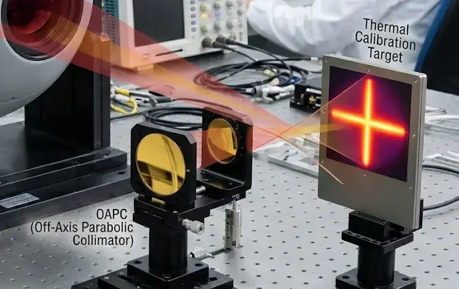
3. Off-Axis Parabolic Collimators (OAPC)
Target plates work well for field checks, but factory calibration requires off-axis parabolic reflective collimators.
Refractive glass collimators bend different wavelengths at different angles due to chromatic dispersion. Parabolic front-surface mirrors coated in gold or protected aluminum reflect all wavelengths identically. Light from a 1535 nm laser, a color daylight camera, and a long-wave thermal core follows the exact same reflection path, projecting an aligned target at optical infinity within a compact room.
EO/IR Gimbal Laser Boresighting Calibration Procedure
Standardizing calibration eliminates guesswork and keeps tolerances within tight milliradian boundaries across production batches.
Step 1: Establish the Optical Anchor
Anchor your primary sensor first. In multi-sensor payloads, the narrow-field-of-view daylight camera generally serves as the baseline because of its superior pixel resolution. Center this camera on the collimator reticle, zero out the gimbal gyros, and freeze the drive motors.
Step 2: Mechanical Trimming and Optical Steering
Next, bring the 1535 nm laser pulse into alignment with that anchor line. Coarse adjustments rely on precision mounting pins or micro-shims under the laser chassis.
Fine optical steering is better handled by rotating dual Risley prisms or adjusting internal piezo-driven folding mirrors. This steers the beam along both azimuth and elevation axes without placing mechanical stress on the primary module casing.
Step 3: Digital Crosshair Calibration
Once the physical laser hits dead-center on the master mark, bring up the thermal feed. Instead of mechanically adjusting the delicate thermal core, shift the thermal processing engine's digital reticle. Repositioning the software crosshair brings the thermal reticle onto the laser's strike position with sub-pixel accuracy.
Step 4: Build Dynamic Lookup Tables (LUT)
As continuous-zoom thermal lenses transition between wide and narrow fields of view, minute mechanical imperfections in the lens barrels cause the optical center to shift slightly—an issue known as optical runout.
During factory calibration, record boresight deviations at multiple zoom positions and write these values to a non-volatile lookup table inside the gimbal controller. As an operator zooms in and out during missions, the firmware shifts the crosshair dynamically to match the true laser impact point.
Sensor Alignment Methods Compared
Optical Window Transmission Loss for 1535nm Laser Transmitters
Housing optronics inside an environmental enclosure shields sensitive electronics from salt mist, sand, and precipitation. That front window introduces distinct optical penalties that degrade ranging performance.
Optical Window Materials
Window selection is always an exercise in balancing optical transmission against physical hardness:
Managing Back-Scatter and Receiver Saturation
Any uncoated optical surface reflects roughly 4% of incident light due to the air-to-glass refractive index step. For a high-energy laser rangefinder, that 4% bounce travels directly back into the receiving optics.
This internal reflection can saturate the receiver's avalanche photodiode (APD), temporarily blinding it right as genuine target reflections begin returning from distant objects. Multi-layer anti-reflective (AR) coatings tailored to 1535 nm are essential to suppress surface reflections below 0.25%, protecting receiver sensitivity and ensuring maximum operational range.
Keeping Sensors Aligned in Harsh Environments
Achieving tight tolerances in a climate-controlled laboratory is one thing; maintaining them on an aircraft wing or an armored vehicle hull is another.
Vibration and Mechanical Shock
Tracked vehicles and rotorcraft subject payload frames to continuous vibration between 50 and 500 Hz, alongside sharp shock loads from rough terrain or weapons fire.
If optics sit in standard friction-held mounts, they will drift. Systems built for high-stress platforms use dowel-pinned structural mounts, thread-locking compounds, and potted laser cavities where crystals and mirrors are bonded inside rigid housings.
Temperature Fluctuations
Airborne platforms frequently take off in 45°C ground heat and climb into -40°C air at high altitudes.
Because aluminum expands and contracts at a rate different from optical glass, these shifts can distort optical mounts and tilt lenses off-axis. Engineers prevent this using athermal optomechanical designs—pairing compensating materials like invar spacers with aluminum sleeves so structural shifts cancel out across the temperature curve.
Custom Optoelectronic Integration with CSOPT Limited
Integrating high-performance rangefinders into compact, multi-sensor gimbals leaves little room for standard, bulky hardware. Tight weight limits, crowded internal spaces, and custom communication busses demand purpose-built optronics.
CSOPT Limited manufactures precision Laser Rangefinder Modules designed specifically for deep integration into electro-optical turrets, thermal sighting gear, and airborne tracking systems.
CSOPT builds Class 1 eye-safe 1535 nm Erbium-glass rangefinders that offer:
Low Beam Divergence: Tightly controlled divergence profiles down to 0.3 milliradians, keeping pulses on target even through narrow thermal fields of view.
Compact Footprints: Space-efficient board-level layouts that slip alongside thermal cores without disturbing gimbal center-of-gravity calculations.
Environmental Stability: Factory-tested operating profiles handling wide temperature spans from -40°C to +60°C without boresight wander.
Custom Engineering Support: From mechanical housing alterations and custom prism mounts to specialized TTL/RS422 serial interfaces, CSOPT adapts its hardware to match your proprietary payload specs.
Discover their full range of integrated laser hardware by visiting https://csopt.cc/.
Maintaining Long-Range Precision
Keeping a 1535 nm laser rangefinder harmonized with an infrared camera requires managing the physics of light, choosing the right window materials, and building rigid mechanical assemblies. When you control thermal-mechanical drift, suppress optical reflections, and apply disciplined multi-step boresighting, your sensor package operates as a unified targeting asset. The result is instant, reliable range data on every single pulse.
Frequently Asked Questions
Why use 1535 nm for ranging instead of 905 nm or 1064 nm?
The 1535 nm wavelength sits in the short-wave infrared band, where light is absorbed by the cornea and lens before reaching the retina. This makes it substantially safer for human eyes than 905 nm or 1064 nm beams, allowing systems to transmit much higher pulse energies over longer distances while maintaining Class 1 eye-safe ratings.
Can an uncooled thermal camera see a 1535 nm laser directly?
No. Standard uncooled microbolometers detect long-wave thermal energy between 8 and 14 microns. They do not register 1.535-micron light unless the laser fires repeatedly at an energy-absorbent target to generate a physical hot spot that the thermal camera can pick up as heat.
How often should an EO/IR gimbal undergo boresight recalibration?
Aerospace platforms typically run digital loop tests before every mission. Full hardware boresighting checks on a collimator bench are standard every 250 to 500 operating hours, or whenever the turret takes a heavy mechanical impact or undergoes modular sensor servicing.
What is the most effective way to prevent laser back-scatter inside gimbals?
Apply narrowband multi-layer anti-reflective coatings to both surfaces of your protective window, optimized specifically for 1535 nm. Positioning the window at a slight tilt relative to the laser axis also deflects internal reflections away from the sensitive receiver photodiode.
Does CSOPT Limited support custom form factor requests for drone gimbals?
Yes. CSOPT produces custom OEM rangefinder modules, adjusting dimensions, optical offsets, mounting configurations, and communication protocols to fit tightly packaged drone and ground-vehicle sensor suites.